Intake/Outtake
Problem Statement: The robot needs to be able to place the samples into the buckets, as well as hang the samples into each basket.
Design Statement: The arm should vertically move the correct amount, the claw should have the proper grooves to grip and release the sample efficiently.

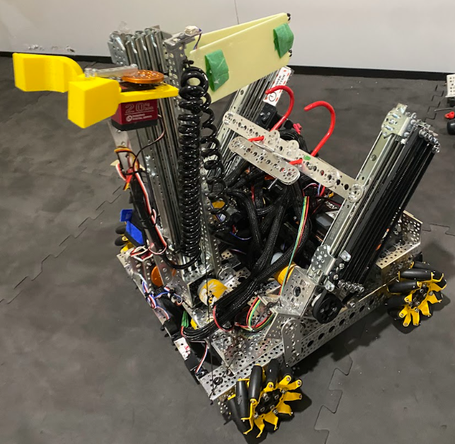
Our intake system uses a custom designed and 3d printed claw and pincer system to hold the sample. The claw contains a triangular shape which perfectly aligns with the sample to provide a proper grip. Each claw is driven by a 20 kg servo. The arm is made of two servos to make separate joints. The first part moves the arm up and down. The next joint is able to control the position of the claw, which helps with the accuracy of our robot. By using two servos to create two joints we are able to be more precise while playing and allows us to pick up specific samples from the center.
Hanging
Problem Statement: The robot needs to be able to obtain an ascent.
Design Statement: The robot should be able to consistency lift off of the field and obtain an ascent.

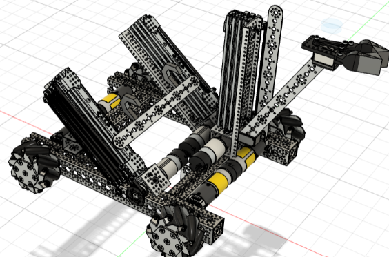
After testing we decided to use a GoBilda 5202 series motor to power our rack and pinion mechanism, which was custom designed and 3D printed. On the sides of each of these racks is a hook attached to a spring. When lifting both of these slides, we push the robot right up to the bar and push the slides through the bar, the hook bending down and then flicking back up latching onto the bar and allowing us to achieve a hang. We also have a middle slide with a third hook to stabilize our hanging.
Drivetrain
Problem Statement: The Robot needs to efficiently move around the playing field to score pixels faster.
Design Statement: The Drivetrain needs to be small and easy to maneuver around the field.
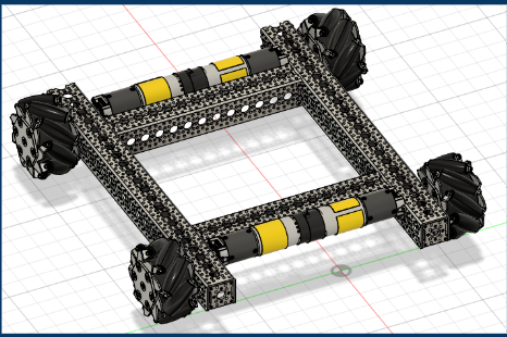
Our drivetrain consists of 4 mecanum wheels separately operated by four Gobilda 5202 435 RPM motors. We use these wheels in order for the robot to be omnidirectional These motors are mounted directly onto the base via face mounts. In addition, all 4 of our wheels run on a direct connection with axles, using an axel to go straight from the motor to the wheel and attaching them together via shaft couplers. We have our drivetrain arranged this way so that we can leave space in the middle for arm to fold in and rest as well as leaving space for our middle slide. We also used encoders on drive motors for better odometry in autonomous mode.
Entire Robot
Problem Statement: The robot needs to efficiently move around the field, while also being able to score samples and samples, and hang off the rungs
Design Statement: The robot’s design needs to be robust, small and easily maneuverable.
Our Robot is made up of 3 main parts, the drivetrain, the hanging, and the arm. Each one of these parts is important for the success of the robot, and all of them work together in harmony. The drivetrain is a 18 by 16 inch chassis which runs on Gobilda 5202 series 13.7 motors. The linear slides are rigged with a rack and pinion, and the arm uses two servos which are each connected to custom printed arms. This arm also has a servo to add a joint and is connected to the slide by another servo, allowing much more freedom in movement.